¶ Practical Example (KRITIS)
¶ Control and monitoring of Marine Lanterns
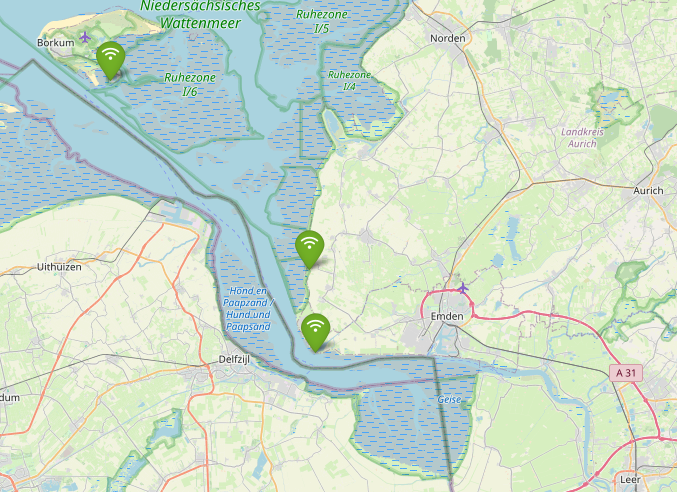
¶ Gateways
Several LoraWan gateways are responsible for the accessibility of a large sea area by LoraWan end devices. The gateways are usually installed on infrastructure at high altitudes, to achieve wide coverage.
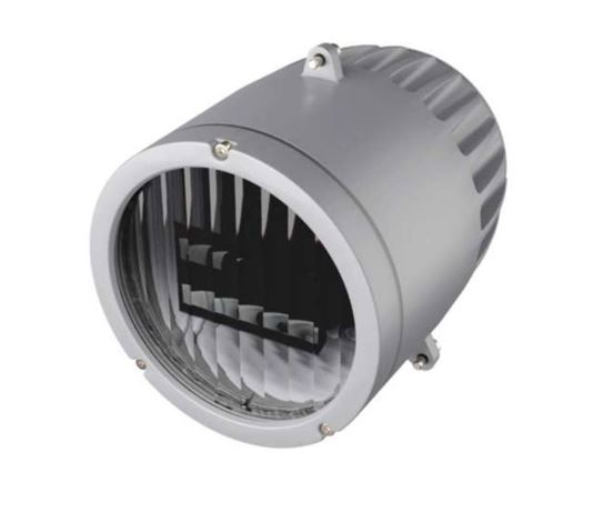
¶ Latern
The following example describes a latern with an integrated Modbus interface. Each ModBUS participant (slave) has a number of registers in its documentation through which data can be read and written. In this application example, a serial ModBUS interface (RS485) is offered by the device.
- Sabik sea lantern with RS485 option (Example)
Here is an excerpt from the documentation with some addresses. In order to be able to transmit these measured values and switching states via LoRaWAN in an energy-saving manner, an interface is required.
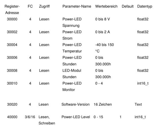
¶ LoraWan Modbus Bridge
- Lobaro Hybrid Gateway (ext. Power, Din-Rail)
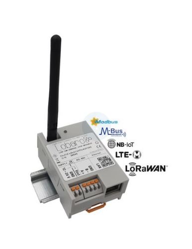
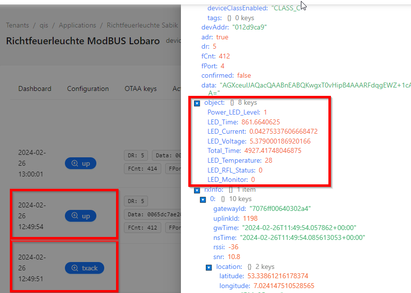
The Lobaro LoraWan-Modbus bridge is configured as "Class C", which regularly reads all relevant data from the registers and transmits it via LoraWan via the installed gateways to the LaraWan Network Server (LNS). This LNS Chirpstack runs in its own data center in a secluded and secured area.
0 0/10 * * * *:R,9600,8E1:fa0400050001,010475300010,01039C400001
fa0400050001 //Reads the operating voltage on the LoraWan Modbus bridge
010475300010 //Reads 10x Analog Input Register
01039C400001 //Reads 1x Holding Register (Lamp Brightness Level)
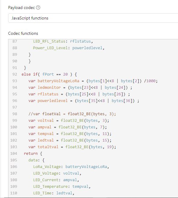
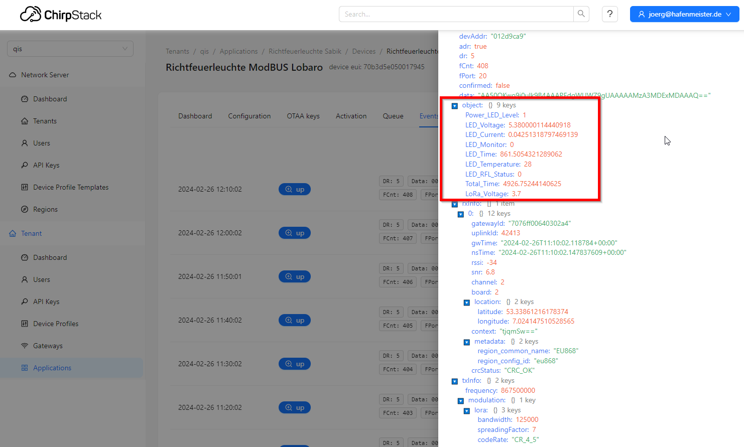
¶ Chirpstack LNS
The data transmitted in this way (Base64) is converted to (HEX) and decoded in the LNS by a stored decoder:
¶ LoraWan Adapter
At the MQTT broker of the LNS, the data is picked up by a LoraWan adapter and further processed.
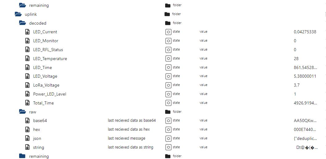
The communication of this adapter with the LNS is bidirectional, so that not only data can be received, but settings and commands can also be sent to the LNS.
The downlink configuration can be set conveniently and individually via a separate dialog page.
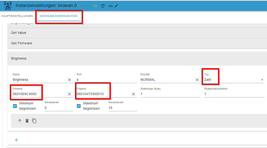
This example shows how the downlink is composed when controlling the brightness level. In the 1st part (Führend) and the value of number converted to HEX, followed by the current retrieval of all other registers (Folgend). As specified by the manufacturer, the level value is limited to between 0 and 15. By configuring the downlink command, a data point is created that allows direct input and execution:
The downlink created:
0601069C40000106010475300010
0601069C4000 // Write Level Register
01 //Value
06010475300010 // Reads 10x Analog Input Register
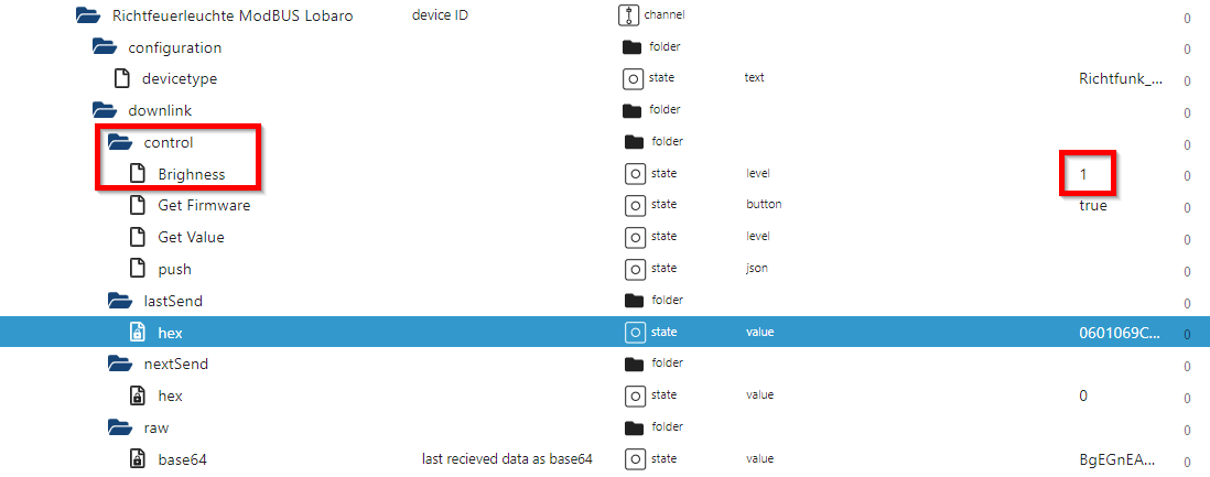
Not only can a value be set via a single downlink, but all relevant data can also be retrieved at the same time.
The response to the command and the retrieval of the registers are also decoded accordingly, picked up by the adapter and written into data points.
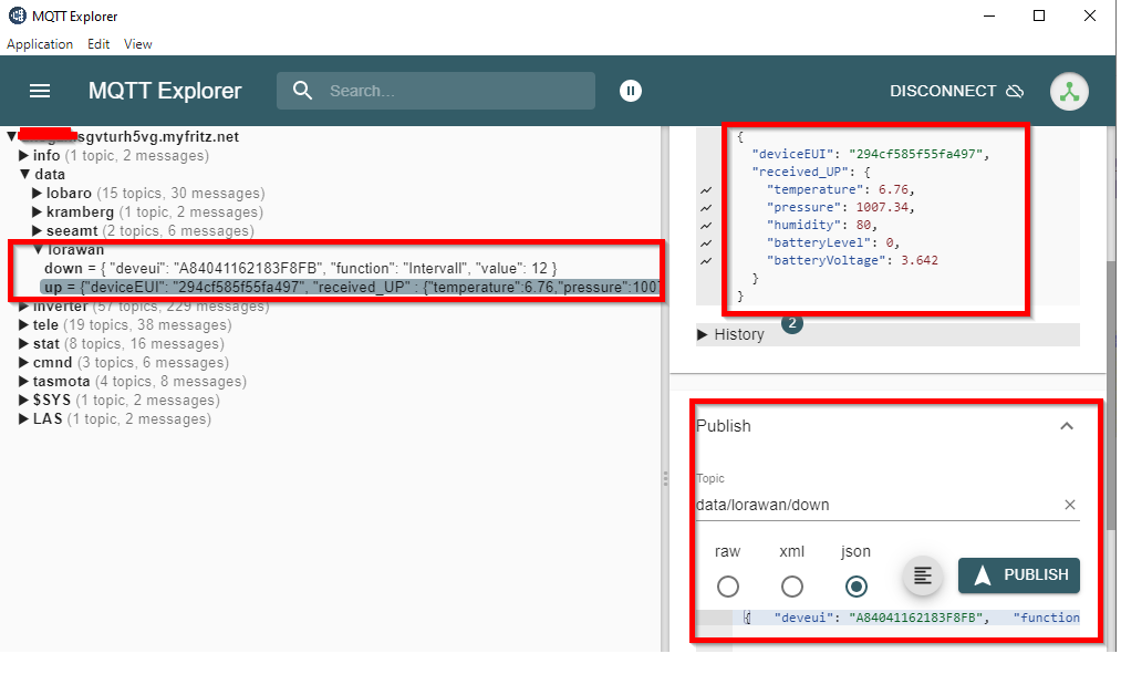
¶ MQTT 2 LoraWan Converter Bridge
¶ up
As an extension to the LoraWan, the “MQTT 2 LoraWan Converter Bridge” can also be set up to ensure an even simpler connection to external applications.
Communication then takes place via MQTT clients, which can handle the entire communication via two interfaces alone.
This would be the [1] interface "up" through which all information coming from the LoraWan adapter is handled:
{
"deviceEUI":"294cf585f55fa497",
"received_UP":{
"humidity":82,
"temperature":11.52,
"batteryVoltage":3.676,
"pressure":1006.28,
"batteryLevel":0
}
}
Arriving here is the (unique) device address and the relevant user data.
¶ down
The MQTT input “down” offers the option of sending commands to the devices. Example:
{
"deviceEUI":"A84041162183F8FB",
"function":"RO1_target",
"value":true
}
The structure of the control command is deviceEUI, (configured) control command, value.
¶ down response
The value must be sent in the correct format (bool, number, string). When you send a “down” command, there is an “up” response. Example response if successful:
{
"deviceEUI":"A84041162183F8FB",
"respone_Down":{
"applicationId":"hafi-ttn-lorawan",
"deviceEUI":"A84041162183F8FB",
"deviceId":"eui-a84041162183f8fb",
"deviceType":"LT22222",
"downlink":"RO1_target",
"value":true,
"received":{
"deviceEUI":"A84041162183F8FB",
"downlink":"RO1_target",
"value":true
}
}
Example response in case of failure:
{
"deviceEUI":"A84041162183F8FB",
"respone_Down_ERROR":"downlink is type boolean, but received string",
"received":{
"deviceEUI":"A84041162183F8FB",
"downlink":"RO1_target",
"value":"false"
}
}